

Melamine chips around CNC-drilled holes when its hard decorative surface fractures before the cutting edge can shear it cleanly. Resin-infused decorative paper is bonded to a particleboard or MDF core. The surface is durable in use but cannot stop a crack once drilling forces lift it from the core.
The usual causes are a worn or unsuitable bit, an incorrect relationship between spindle speed and plunge feed, tool run-out, poor support at breakthrough, or a weak or uneven panel core. The location of the damage is the quickest clue. Chipping at the entry side usually points toward tooling or run-out. Chipping at the exit side usually points toward breakthrough pressure or inadequate backing.
Diagnose the Chipping Before Changing the Settings
Changing several parameters at once may produce one clean hole, but it does not create a repeatable process. First inspect where and how the defect appears.
| What you see | Most likely causes | First check |
|---|---|---|
| Chipping only at the entry | Dull scoring edges, unsuitable drill geometry, run-out | Fit a known-good laminate drill and inspect the holder |
| Chipping only at the exit | Unsupported panel, fast breakthrough feed, dust under the workpiece | Restore full support beneath the hole |
| Chipping on both faces | Worn tool, severe vibration, mismatched speed and feed | Isolate the tool before changing the program |
| Damage on one side of the hole | Radial run-out, excessive tool projection, panel movement | Measure run-out and check clamping |
| Good holes at first, then worsening quality | Tool wear, heat or poor chip evacuation | Compare the first and later holes in the run |
| Problem begins with a new board batch | Core density, surface bond or flatness variation | Drill old and new material under identical conditions |
Do not judge the process from one hole. Repeat the best setting across enough holes to reveal heating, dust accumulation or wear.
Why the Drill Bit Matters So Much
A standard twist drill may lift a brittle coating before the circumference is fully severed. A purpose-designed brad-point, V-point, dowel or through-hole bit uses its outer geometry to score the perimeter earlier.
For melamine-faced boards, select a carbide-tipped or solid-carbide tool intended for laminated panels. Technical processing guidance recommends low cutting pressure, good chip removal and precise clamping.
Match the bit to the operation:
- Brad-point or dowel drills suit clean-entry blind holes.
- Dedicated through-hole bits suit panels with two visible faces.
- Solid-carbide bits offer rigidity and wear resistance for small, high-volume holes when run-out is controlled.
- End mills can interpolate holes on a router spindle, but cannot copy drill-block settings.
Inspect the outer scoring edges under magnification. A bit may still produce the correct diameter after losing the sharpness needed for a clean surface.
Do Not Copy an RPM Without Identifying the Cutting Unit
Drilling advice often appears inconsistent because a CNC drill block and router spindle are different systems. A boring head runs dedicated drills at moderate speed; a router spindle often runs an end mill much faster.
The distinction can be seen on the CAELUS D5S CNC 6-Sided Drilling Center. Its boring head is specified at 4,500 rpm for standard drills, while its milling spindle operates at an adjustable 12,000–18,000 rpm. Those numbers are not competing recommendations; they belong to different tools and operations.
Start with the range supplied by the tool and machine manufacturer. Then evaluate feed per revolution instead of RPM alone:
Feed per revolution = plunge feed ÷ RPM
For example, 600 mm/min at 6,000 rpm produces 0.10 mm per revolution. Raising speed to 12,000 rpm while retaining that feed halves the value to 0.05 mm. The extra rubbing can produce dust, heat and faster wear.
The target is a clean chip and stable hole edge, not the highest spindle speed. When testing, change one variable at a time and record the tool, material batch, RPM, plunge feed, hole depth and result.
Support the Exit Side During Through-Drilling
Exit-side chipping happens as the remaining core becomes too thin to resist the drill's axial force. If there is a gap beneath the panel, the last section bends and breaks instead of being cleanly cut.
A backer or spoilboard works only when flat and in continuous contact. Grooves, dust, panel bow and weak hold-down can create an unsupported area beneath the hole. Clean the table and check whether defects follow one area of the bed.
Where the control allows it, reduce plunge feed only in a short breakthrough zone. This lowers exit force without slowing the whole cycle. Pecking helps when chips pack in a deep hole, but unnecessary re-entry adds rubbing and time.
For a center partition with two visible faces, test a dedicated through-hole drill first. Drilling halfway from each face can produce excellent edges, but manual flipping adds handling and a second reference setup. At production volume, upper and lower drilling units provide a more repeatable route.
Check Run-Out, Tool Projection and Panel Movement
Run-out turns a cutting action into a repeated impact. Instead of both edges sharing the load, one edge strikes the coating more heavily and can create a chipped crescent on one side of the hole.
Clean the collet, holder and shank. Check for wear, use the correct holder, and keep tool projection short. Measure total indicated run-out at the shank and investigate any increase from the machine's known-good baseline.
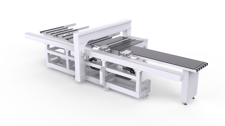
Also confirm that the panel remains stationary during drilling. Stable support and controlled clamping matter as much as positioning accuracy. CAELUS six-sided drilling centers use automatic grippers and transitional air-flotation tables to support panel movement and positioning.
On the D5S, the specified panel range is 200–2,800 mm long, 50–1,220 mm wide and 9–60 mm thick, with permitted panel unevenness of no more than 0.3 mm. Testing the smallest, narrowest and least-flat production parts is therefore more meaningful than demonstrating only an ideal full-size panel.
A Practical Seven-Step Shop Test
- Photograph the entry and exit of the failed hole and mark the panel location.
- Record the board type, thickness and batch, plus the tool number and accumulated hole count.
- Install a clean, known-good drill of the correct geometry without changing the program.
- Inspect the holder, minimize projection and measure run-out against the normal baseline.
- Restore continuous backing and remove dust beneath the drilling area.
- Test a small matrix within the approved tool range, changing only RPM or plunge feed in each run.
- Repeat the best combination across a longer sequence before releasing production.
For visible holes, record chipped holes per 100 and maximum chip width under consistent lighting and magnification. These measurements are more useful than "looks better" and reveal deterioration as the tool wears.
When the Machine Becomes Part of the Problem
A new machine will not compensate for a dull bit or defective board. It becomes relevant when the existing process cannot provide stable support, controlled upper and lower drilling, repeatable recipes or consistent part positioning.
A CNC 6-sided drilling machine processes the top, bottom and four edges from one reference, reducing flipping and re-clamping. For a purchasing test, provide your actual melamine, thickness range, smallest part and hole files. Request the drill type, RPM, feed, sample quantity and defect rate.
CAELUS offers the flexible D5S CNC 6-Sided Drilling Center, automated single-channel D5A CNC Automated 6-Sided Drilling Center and dual-channel D6A CNC Dual Channel 6-Sided Drilling Center for different production volumes. The correct choice depends on panel mix, daily output, software, floor space and automation plans, not on chip-out alone.
FAQ
Q1. Why does melamine chip only on the bottom of a hole?
A: Exit-side chipping usually means poor backing or excessive breakthrough force. Check spoilboard grooves, dust, panel bow and exit feed.
Q2. Which drill bit is best for CNC drilling melamine?
A: Use a sharp carbide bit designed for laminates. Brad-point bits suit blind holes; through-hole bits suit panels with two visible faces.
Q3. Is higher RPM better for clean melamine holes?
A: Not automatically. Drill blocks and router spindles use different ranges. Evaluate the tool specification, plunge feed and chip formation together.
Q4. How can I tell whether the board or CNC drilling machine is responsible?
A: Run old and new panels with the same tool and program, then repeat with a known-good bit. Change one variable at a time.
Q5. Is peck drilling necessary for melamine-faced panels?
A: Only when hole depth causes chip packing. Unnecessary pecking adds rubbing, cycle time and wear at the hole mouth.
Q6. Can a CNC 6-sided drilling machine prevent chip-out?
A: A CNC 6-sided drilling machine improves support, clamping and process consistency, but cannot compensate for a dull tool, unsuitable geometry or defective material.
Q7. What should I send a CNC 6-sided drilling machine manufacturer for a test?
A: Send actual panels, thicknesses, smallest parts, hole files and daily volume. Request the tested tool, RPM, feed, sample size and defect rate.
Conclusion
The fastest fix is not always a new RPM. Start with the location of the damage, identify whether the hole is produced by a boring head or spindle, verify the cutting edge and run-out, then restore support beneath the panel. A short controlled test will reveal more than a long series of random adjustments.
If chipping is exposing limits in support, handling or process consistency, send CAELUS your panel specifications, drilling file, daily volume and defect photos. Our application team can recommend a test plan and an appropriate CNC 6-sided drilling configuration based on the parts you actually produce.